


Description
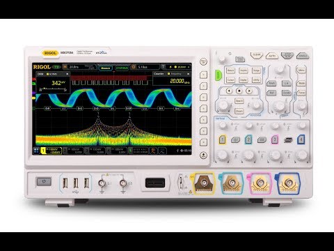
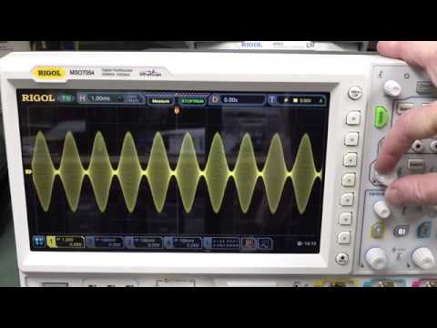
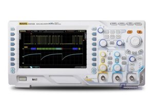
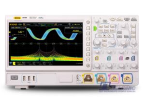
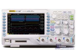
Rigol DS7014 Digital Oscilloscope
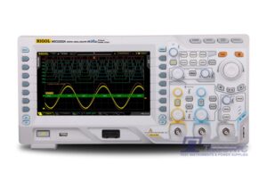
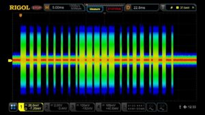
The DS7014 is a 100MHz, 4CH multifunctional, high-performance, Digital Oscilloscope based upon Rigol's new UltraVision II technology. Integrating up to 6-off independent instruments into one, the MSO/DS7000 series offers a high sample rate / bandwidth ratio, high memory depth, clear touch-screen display, excellent waveform capture rate and powerful data analysis functions. Many of its specifications are industry leading. These instruments are expected to be popular for R&D, universities, production, quality control, communications engineering, automotive engineering, aerospace engineering, industrial and power markets.
Features:
- 100MHz bandwidth (bandwidth upgrade options available)
- 4 analogue channels & 1 EXT channel
- Up to 10GSa/s real-time sample rate
- Up to 500Mpts memory depth (optional)
- High waveform capture rate (over 600,000 waveforms per second)
- Up to 450,000 frames of hardware real-time and ceaseless waveforms recording and playback functions
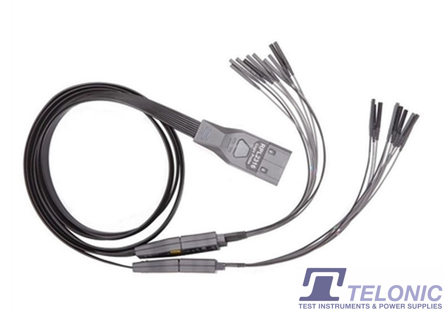
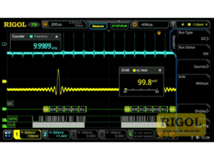
- Integrates up to 6 independent instruments into 1: Digital oscilloscope, 16-channel logic analyser ('MSO' models only), arbitrary waveform generator (optional on 'MSO' models only), digital voltmeter, 6-digit frequency counter & totalizer and protocol analyser
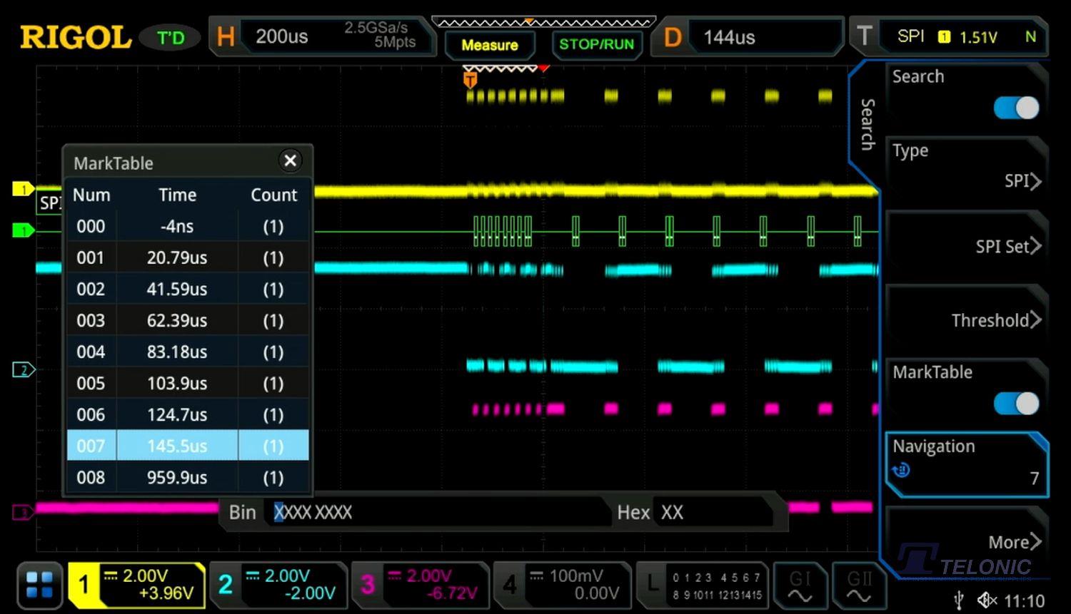
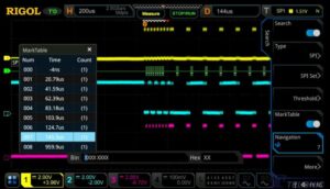
- A variety of serial protocol triggers and decodes
- Auto measurement of 41 waveform parameters; full-memory hardware measurement function
- A variety of math operations, built-in enhanced FFT analysis and peak search function
- Waveform histogram analysis (standard)
- Independent search, navigation keys and event table
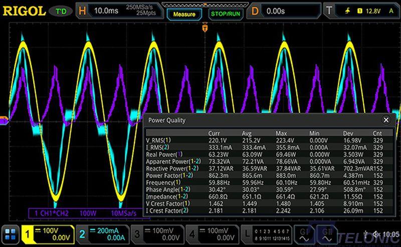
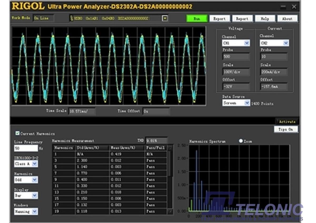
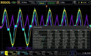
- Built-in advanced power analysis software (option)
- User-defined one-key quick operation
- 10.1" capacitive multi-touch screen, 256-level intensity grading display, with colour persistence
- Web Control remote command
- Unique online version upgrade
- Novel and delicate industrial design, easy to operate
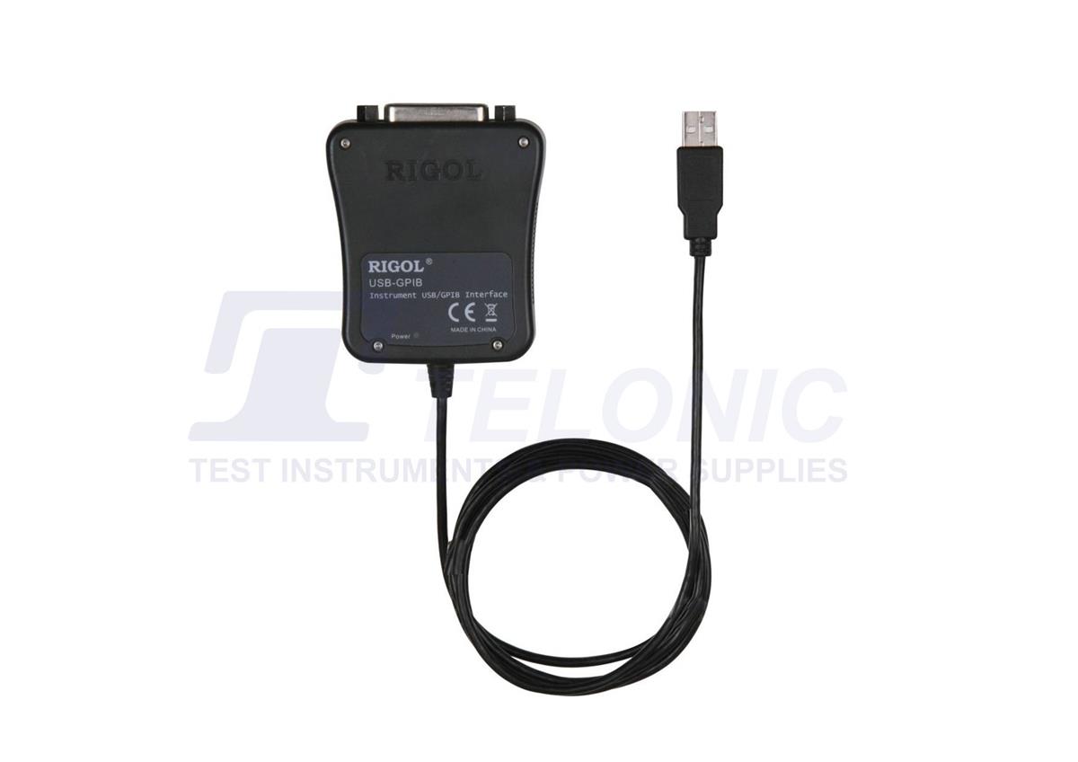
- Connectivity: USB HOST&DEVICE, LAN(LXI), HDMI, TRIG OUT and USB-GPIB
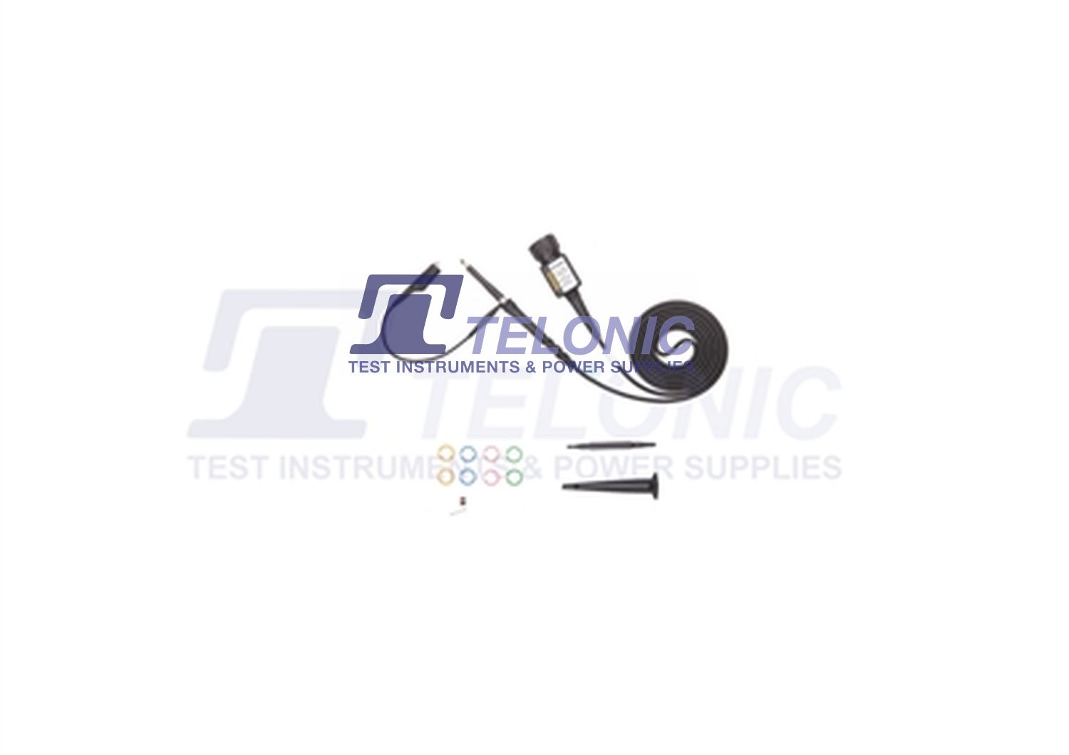
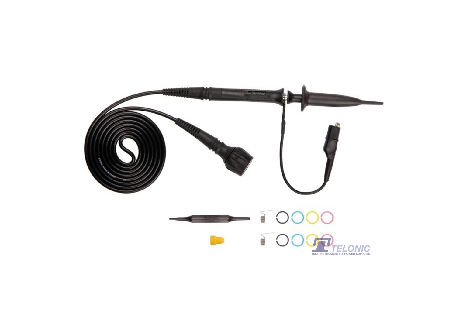
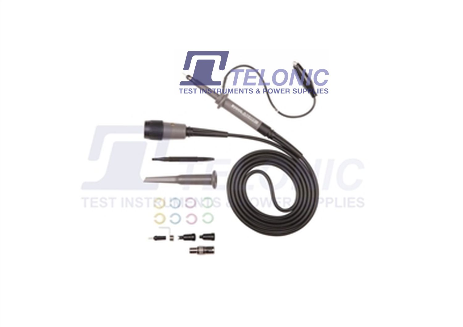
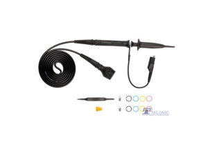
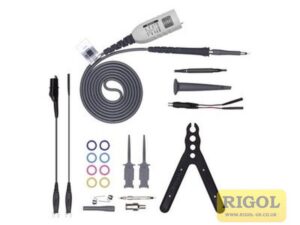
- Supplied with... 4-off passive probes (500MHz), USB cable, UK & European mains leads, front panel cover, quick guide
- Options include... Bandwidth upgrades, memory upgrades, built-in power analysis, Telonic Standard Calibration (traceable to UK national standards), RCL 17025 Calibration
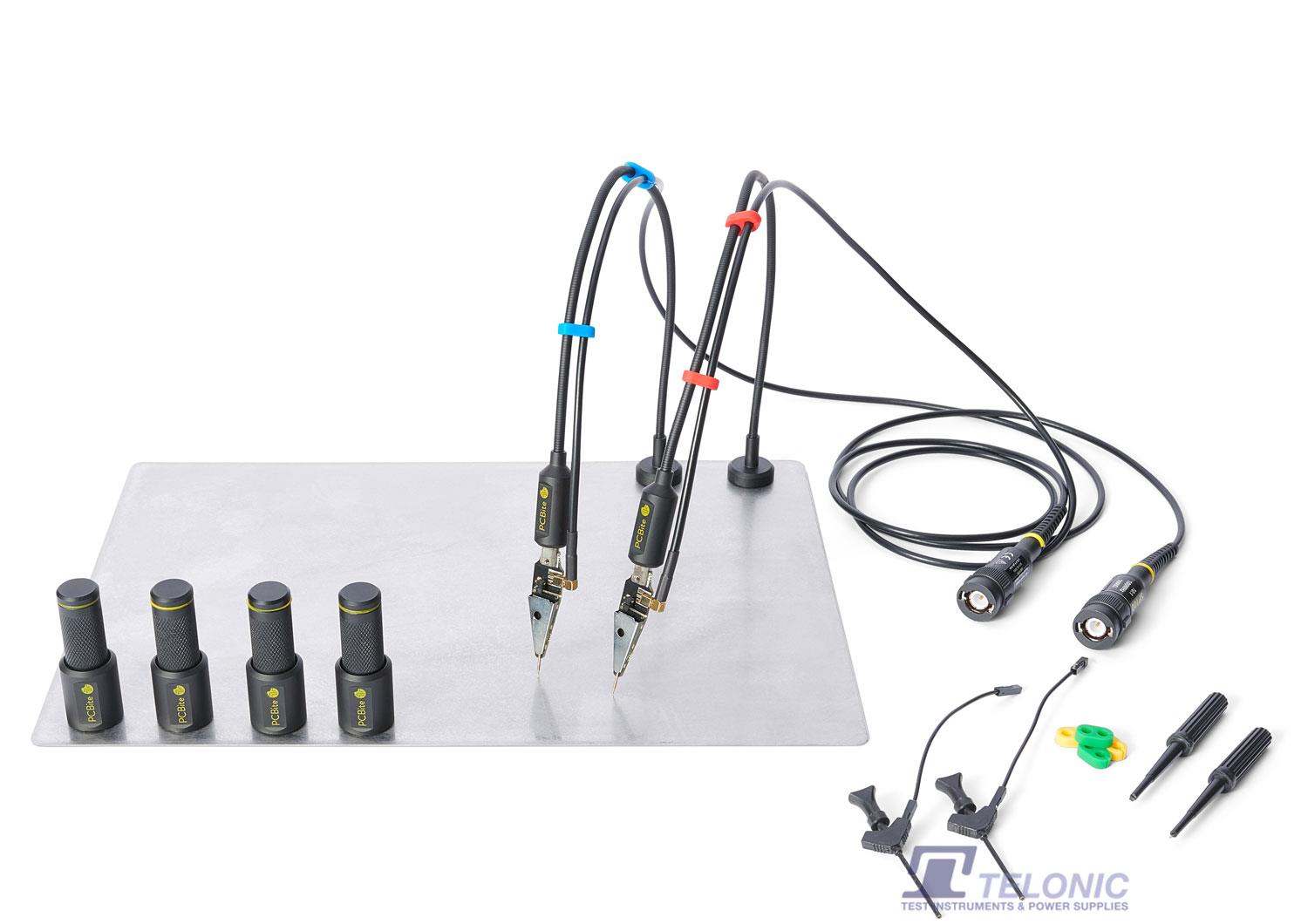
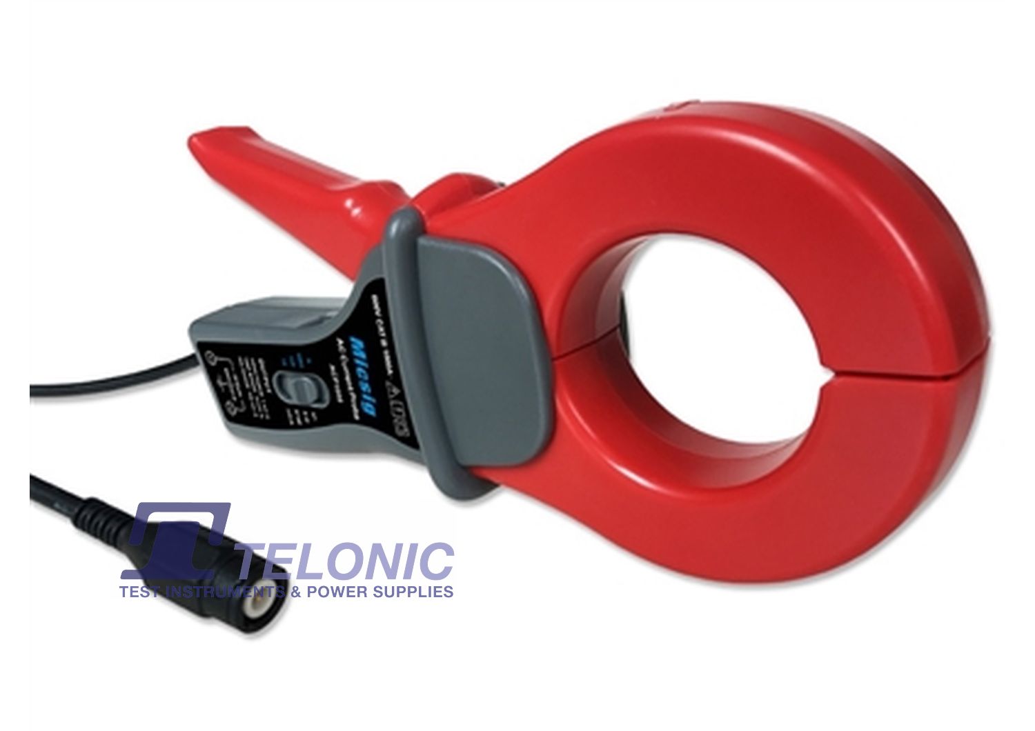
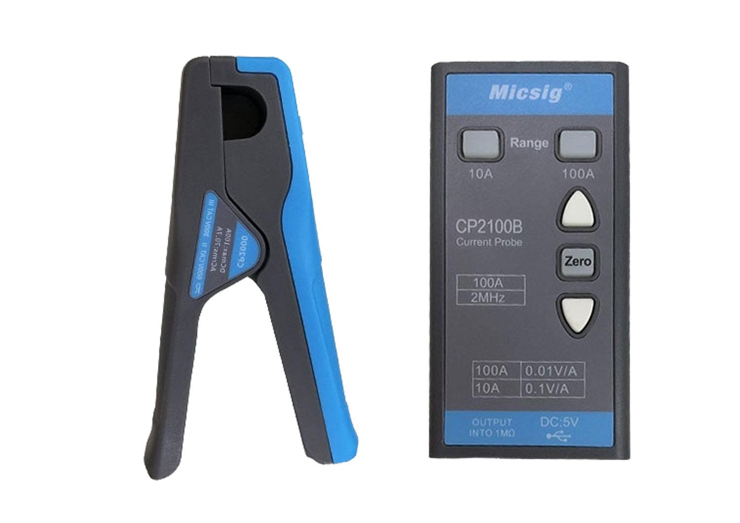
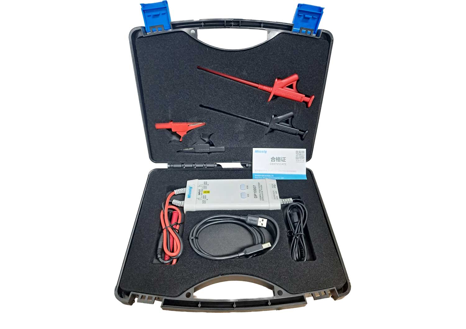
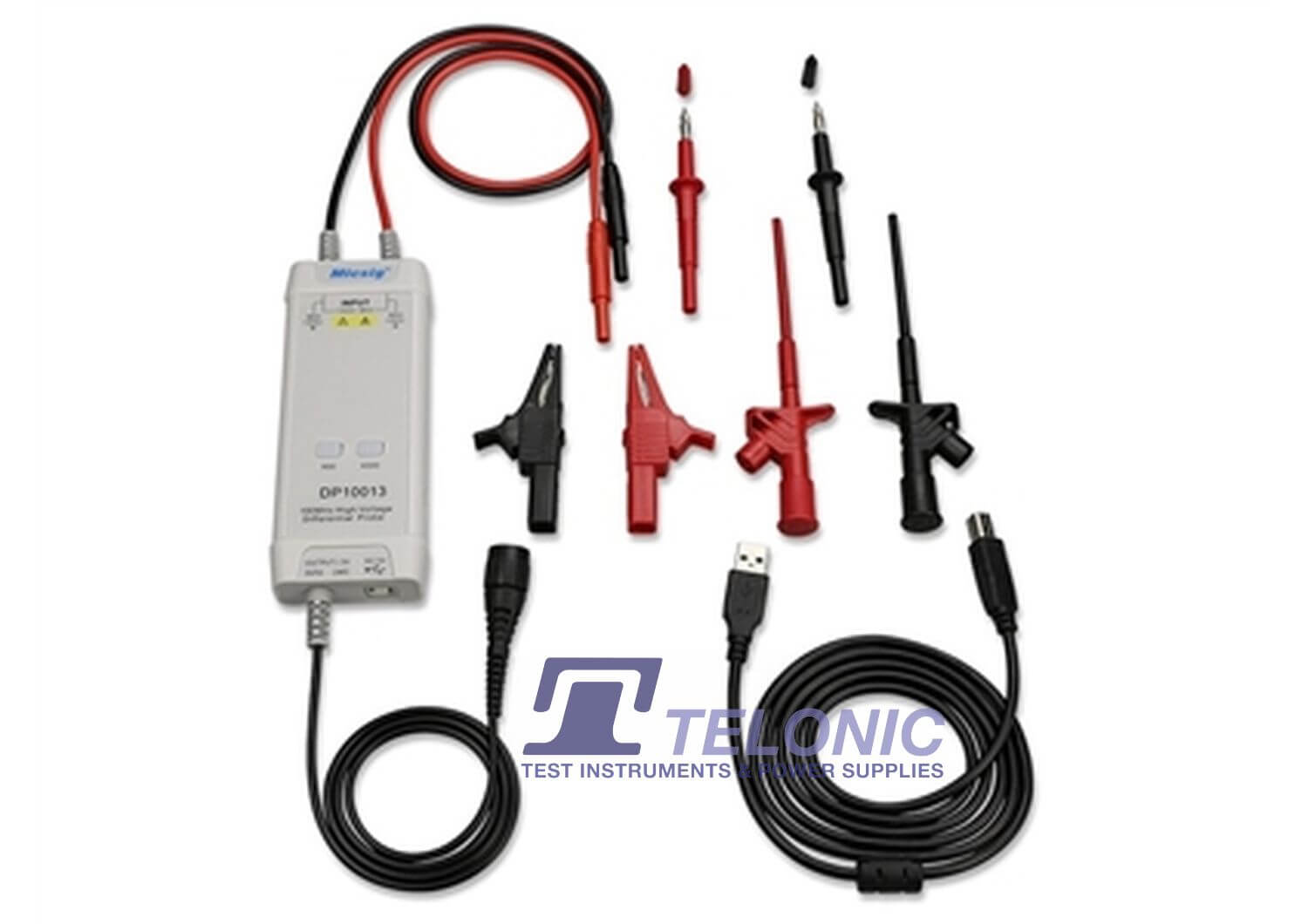
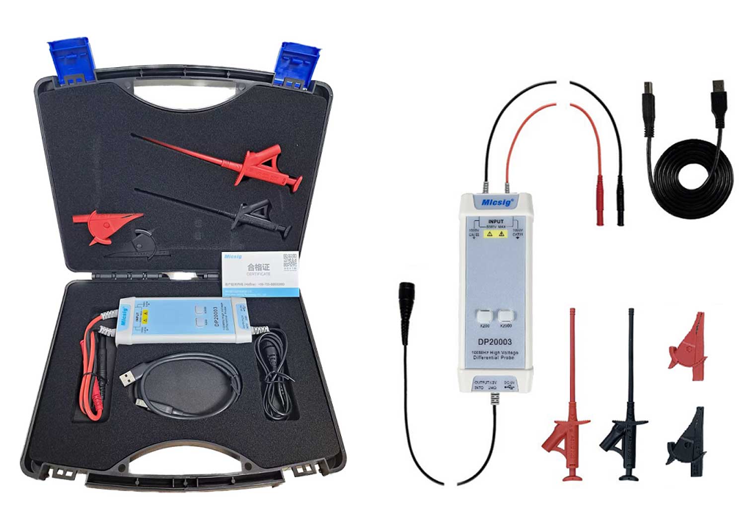
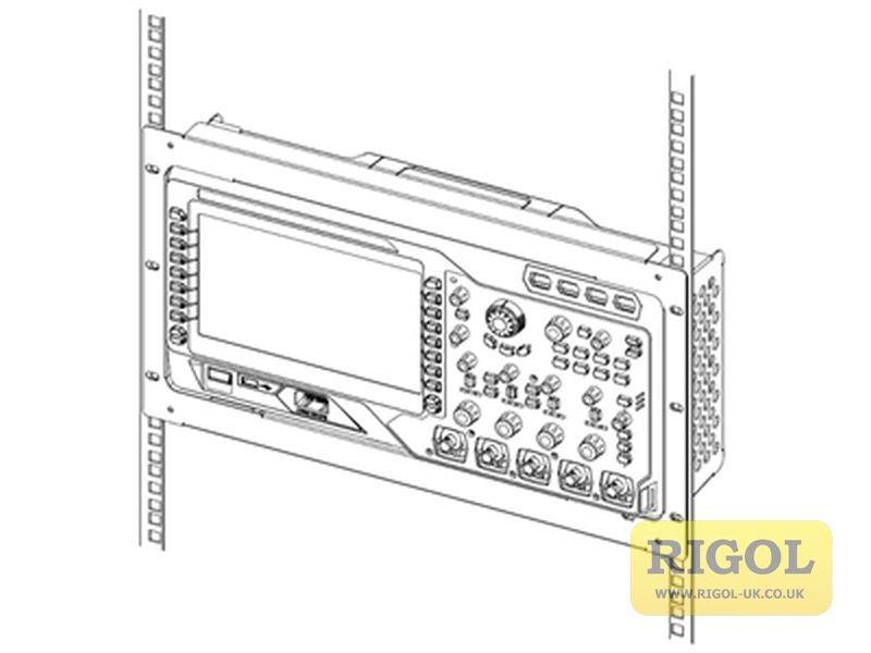
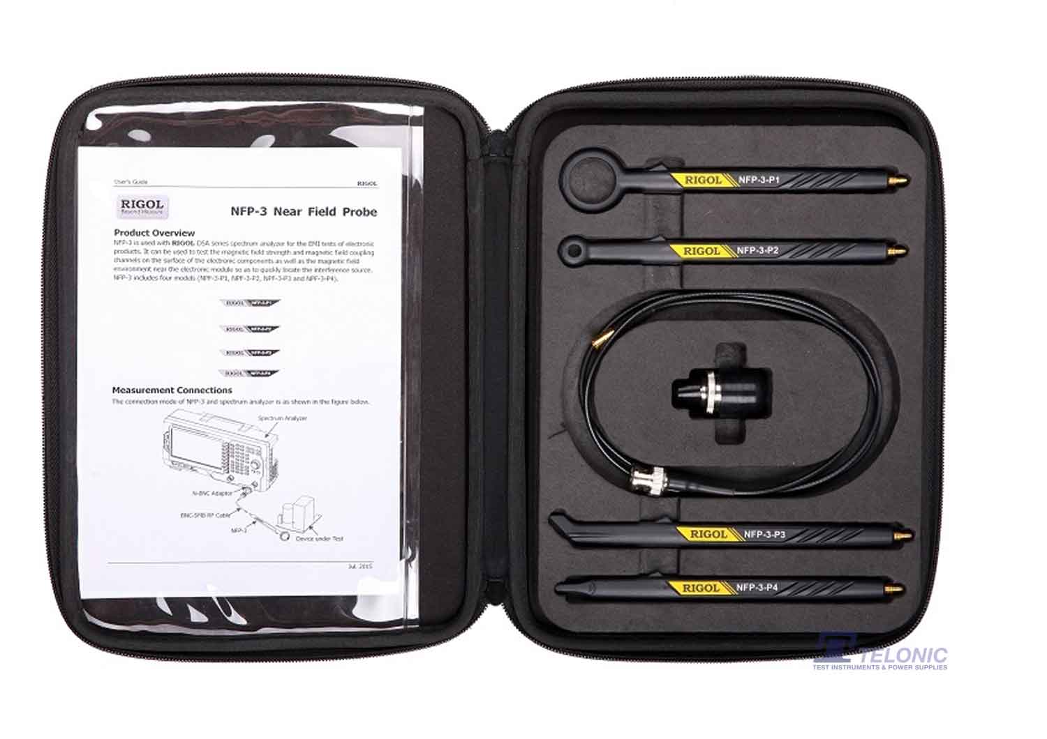
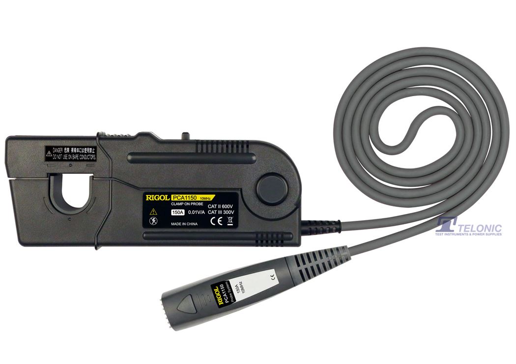
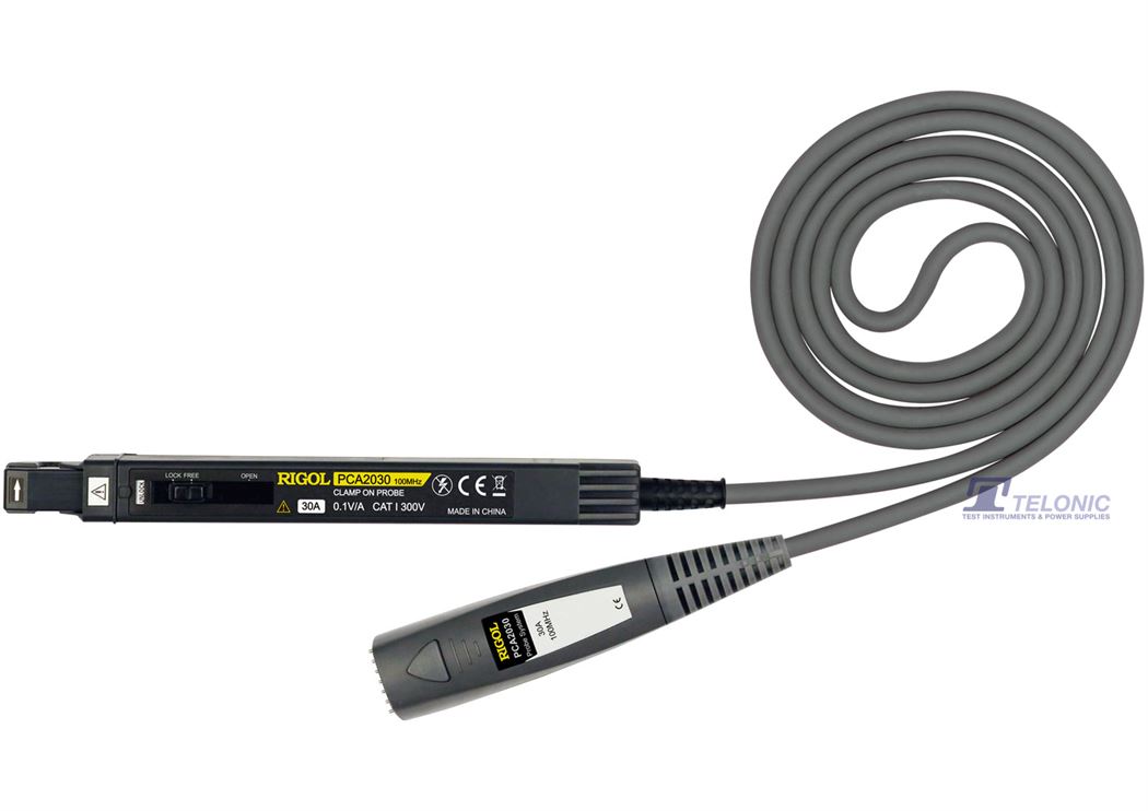
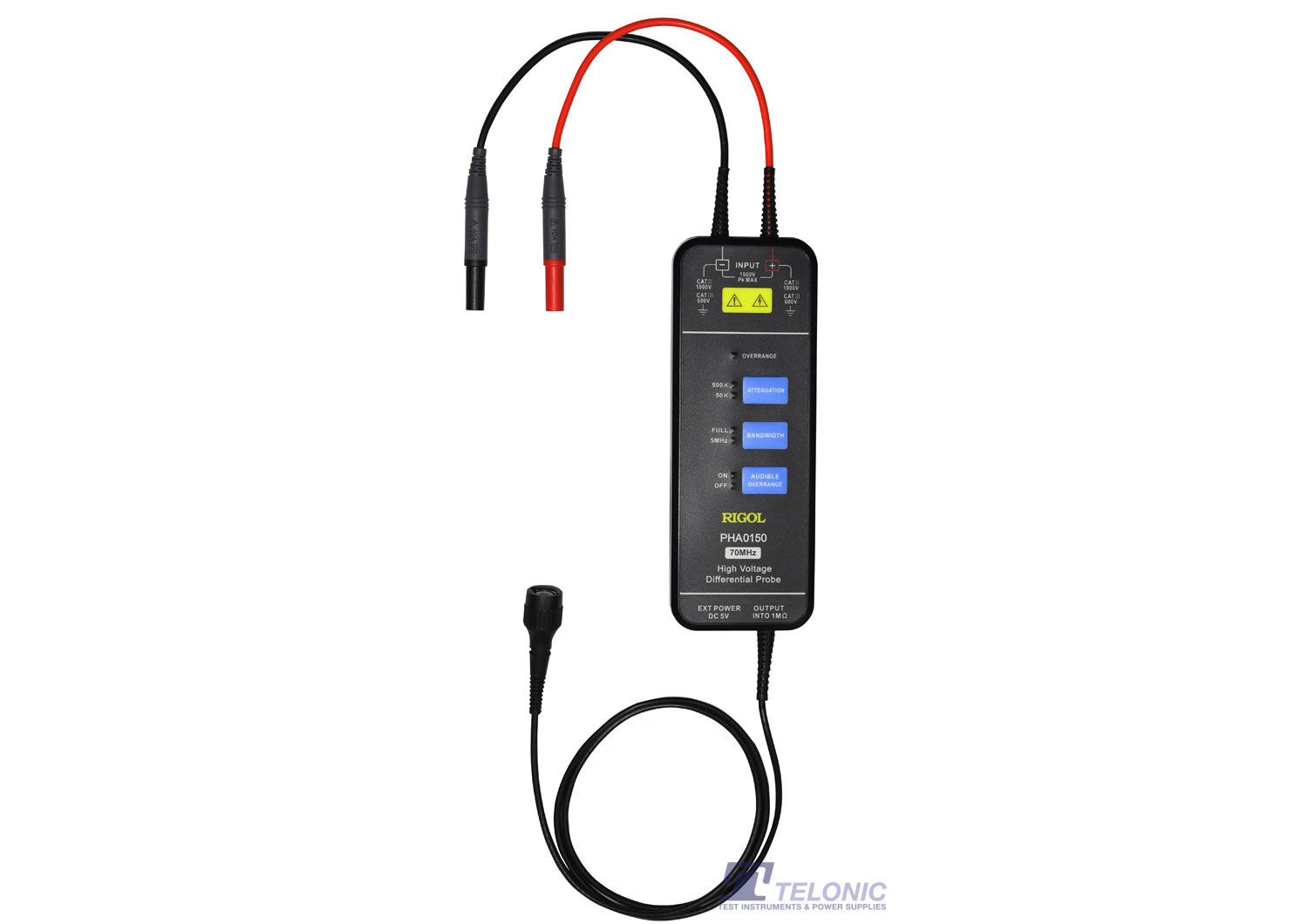
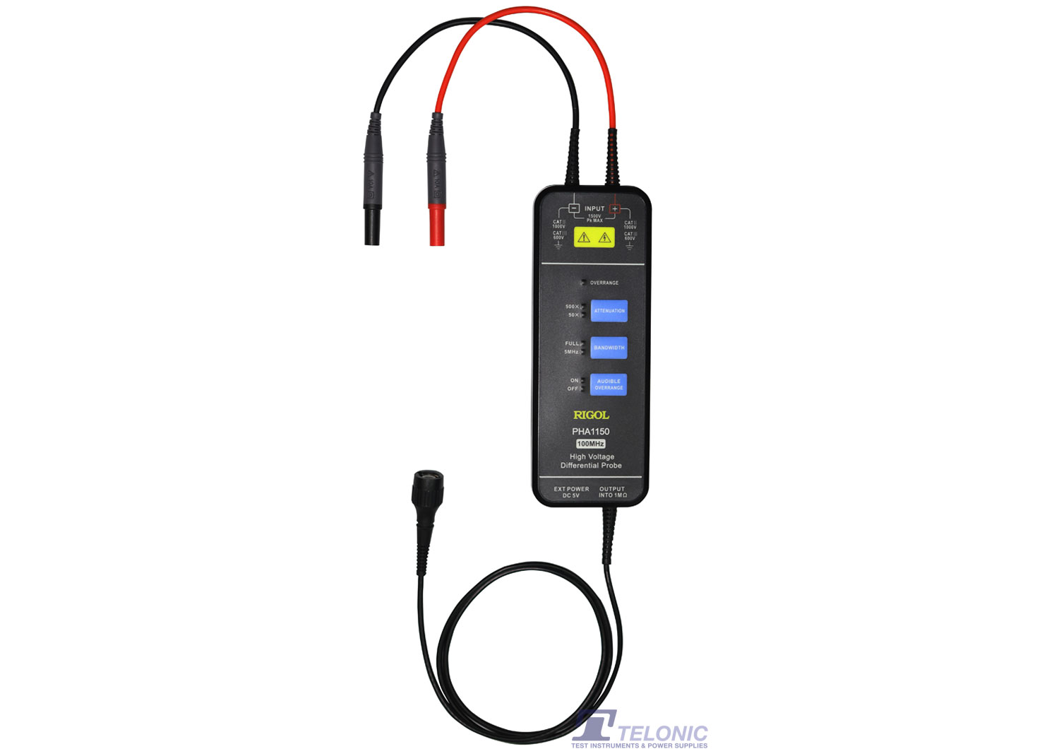
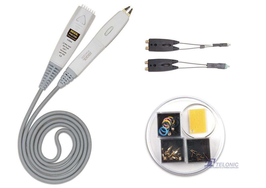
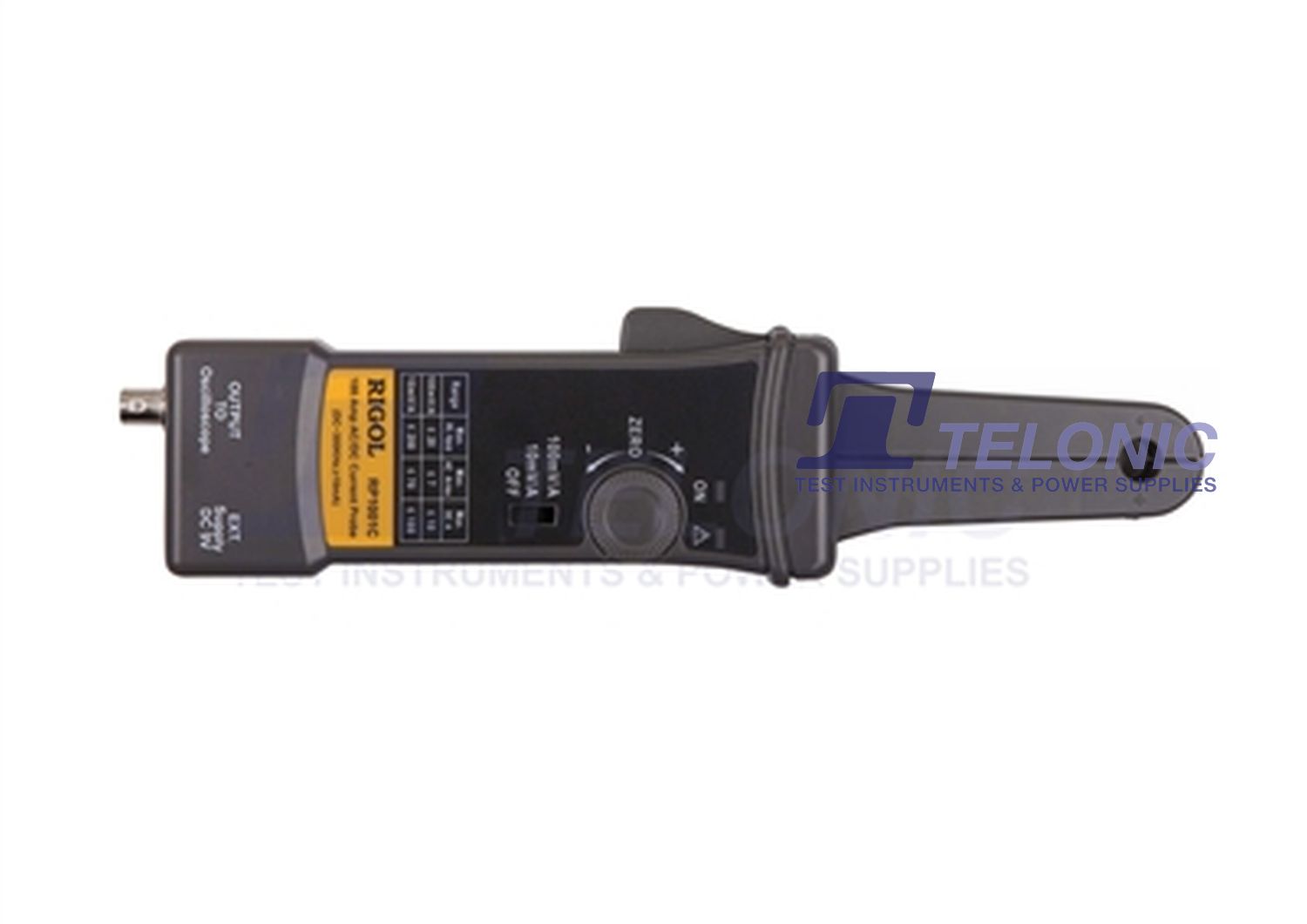
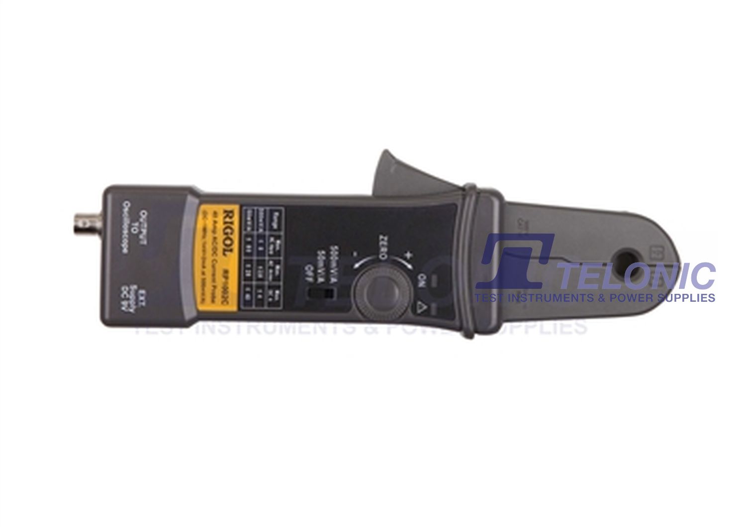
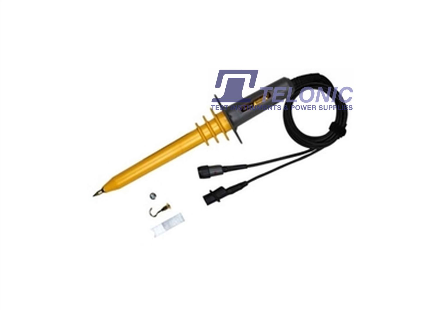
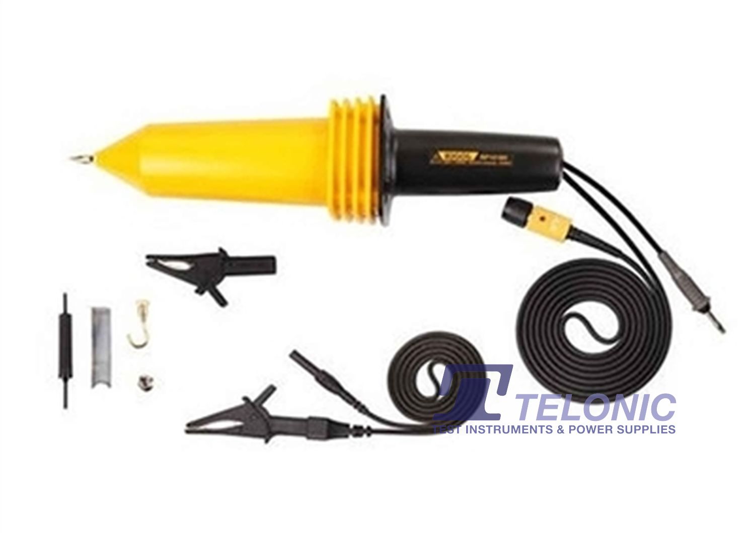
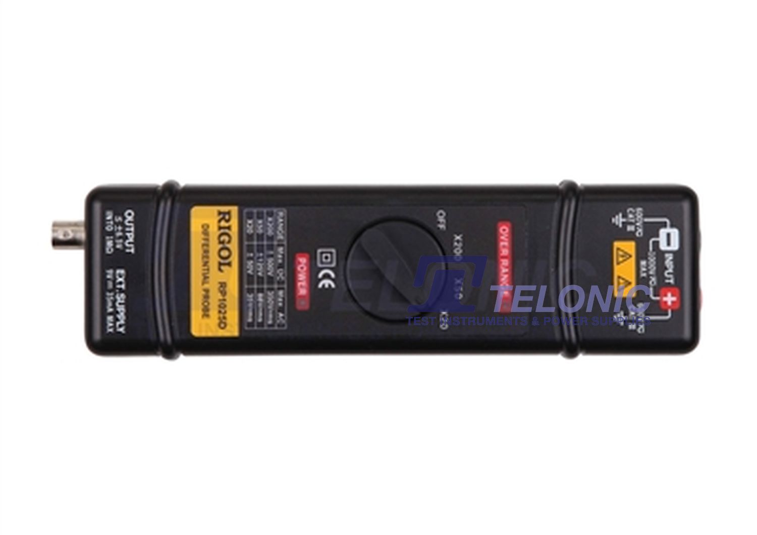
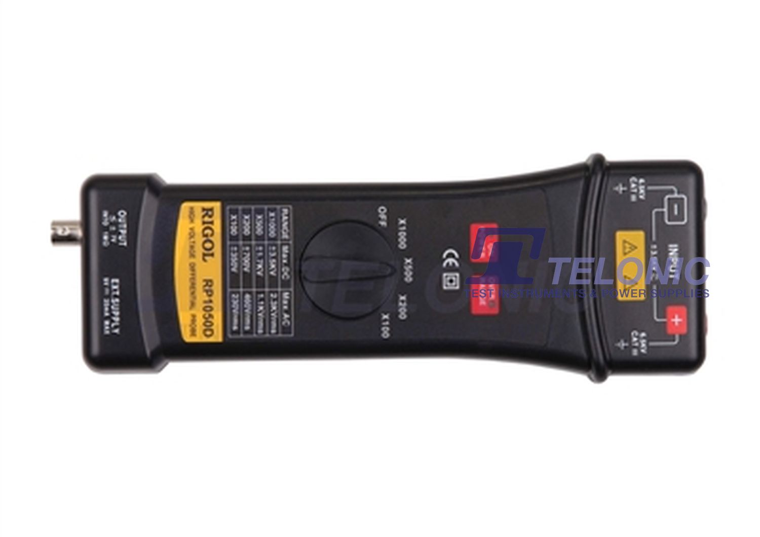
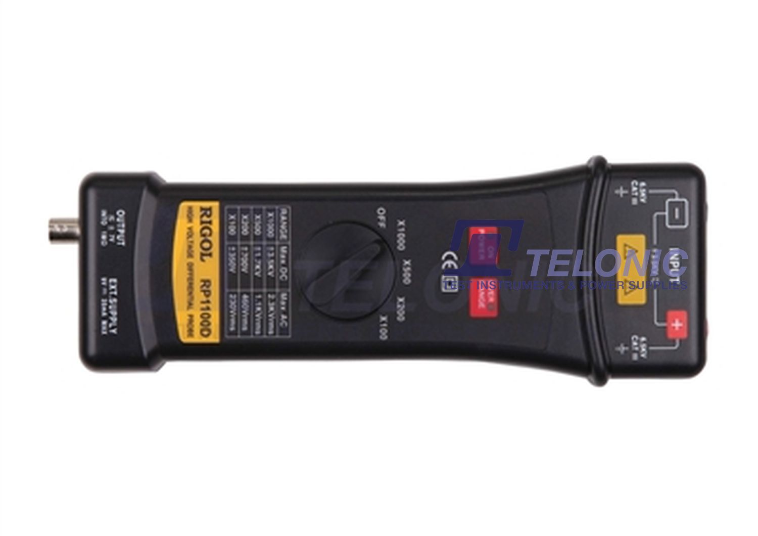
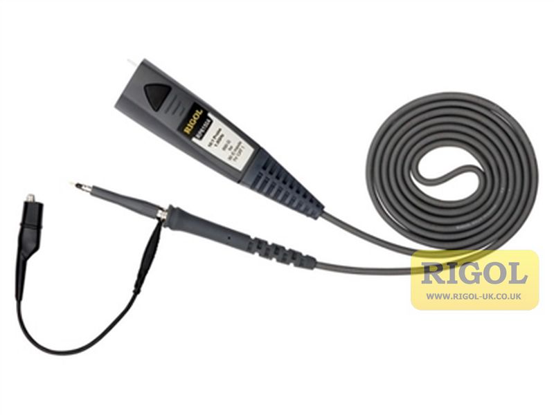
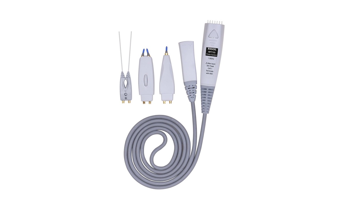
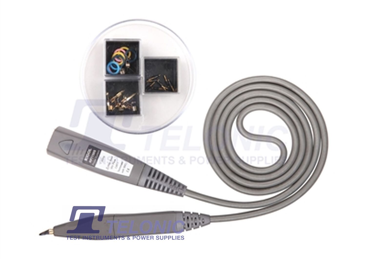
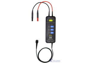
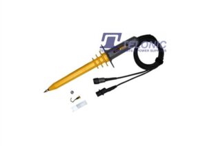
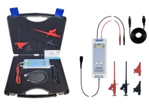
- Optional accessories include... High-voltage probes, high-voltage differential probes, current probes, rack mount kit
Rigol DS/MSO7000 Oscilloscope Comparison Table
| Model | Channels | Bandwidth | Max Sample Rate | Memory | Waveform Refresh Rate |
|---|---|---|---|---|---|
| DS7014 | 4 Analogue | 100MHz | 10GSa/s | 500Mpts Analogue, 62.5Mpts Digital | 600,000wfm/s |
| MSO7014 | 4 Analogue, 16 Digital | 100MHz | 10GSa/s | 500Mpts Analogue, 62.5Mpts Digital | ≥600,000wfm/s |
| DS7024 | 4 Analogue | 200MHz | 10GSa/s | 500Mpts Analogue, 62.5Mpts Digital | 600,000wfm/s |
| MSO7024 | 4 Analogue, 16 Digital | 200MHz | 10GSa/s | 500Mpts Analogue, 62.5Mpts Digital | ≥600,000wfm/s |
| DS7034 | 4 Analogue | 350MHz | 10GSa/s | 500Mpts Analogue, 62.5Mpts Digital | 600,000wfm/s |
| MSO7034 | 4 Analogue, 16 Digital | 350MHz | 10GSa/s | 500Mpts Analogue, 62.5Mpts Digital | ≥600,000wfm/s |
| DS7054 | 4 Analogue | 500MHz | 10GSa/s | 500Mpts Analogue, 62.5Mpts Digital | 600,000wfm/s |
| MSO7054 | 4 Analogue, 16 Digital | 500MHz | 10GSa/s | 500Mpts Analogue, 62.5Mpts Digital | ≥600,000wfm/s |


")


 Rigol MSO/DS7000 Datasheet


Reviews
There are no reviews yet.